
A free-body diagram can look almost too simple: a box or dot surrounded by arrows. Yet one missing or misdirected arrow can ruin every equation that follows. If you want to learn how to draw a free body diagram correctly, the key is not artistic skill. It is learning to isolate one system and show only the external forces acting on it.
The University of Illinois mechanics reference describes a free-body diagram, or FBD, as a representation of the applied forces, moments, reactions, and constraints acting on a chosen body. That is why the method works: it removes unnecessary visual information so Newton’s laws can be applied to a clearly defined system.
What a Free-Body Diagram Actually Represents
A free-body diagram is not a detailed picture of the entire physical scene. It is a force model of one object or selected system.
You mentally “cut” that object away from everything touching or influencing it. The floor disappears, but its push remains as a normal-force arrow. A rope disappears, but its pull remains as tension. Earth is not shown, but its gravitational force remains as weight.
OpenStax explains that an FBD should contain the external forces acting on the body of interest. Once those forces are identified, equilibrium can be analyzed using zero net force, while accelerating objects can be handled with Newton’s second law.
How to Draw a Free Body Diagram in Six Reliable Steps
1. Choose the system before drawing arrows
Decide exactly what you are analyzing. It might be a crate, car, hanging mass, person in an elevator, or an entire connected assembly.
A particle-like object can usually be represented by a dot or simple box. For rigid-body problems involving rotation, keep enough of the object’s shape to show where forces or moments act.
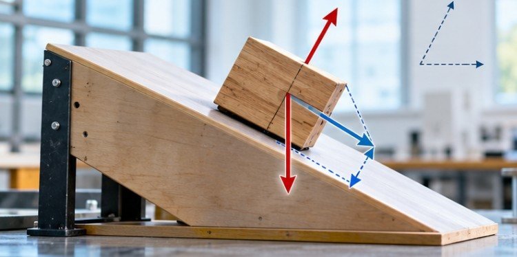
MIT engineering materials similarly treat isolation of the selected structure or body as the foundation for an accurate FBD. You can solve inclined plane problems with friction with ease.
2. Identify every external interaction
Before drawing forces, ask what is interacting with the object.
Gravity represents interaction with Earth. Contact with a surface can produce a normal force and possibly friction. A cable can create tension. A spring, hand, motor, fluid, or another object may produce an additional applied force.
Do not invent a force simply because an object is moving. Motion itself is not a force.
3. Replace each interaction with a force arrow

Draw one vector for each external force and point it in the direction the force acts on your selected object.
Weight points vertically downward near Earth’s surface. A normal force acts perpendicular to a contact surface. Tension pulls along a rope or cable. Friction acts parallel to the surface and opposes relative sliding or the tendency to slide.
Georgia State University’s HyperPhysics describes the same principle as removing the surrounding objects while retaining the forces acting on the body.
4. Label every force clearly
Common labels include W or Fg for weight, FN for normal force, T for tension, Ff for friction, and Fapp for an applied force.
Source-based labels can be even clearer in complicated problems. For example, “force of table on box” tells you exactly which interaction the arrow represents.
5. Add coordinate axes that simplify the problem
For an object on a flat floor, horizontal x and vertical y axes are usually convenient.
On an inclined plane, it often makes more sense to rotate the coordinate system so the x-axis follows the slope while the y-axis runs perpendicular to it. The actual forces do not change; only the way you calculate their components changes.
6. Check the diagram before writing equations
Ask three questions:
Does every arrow represent a force acting on the selected object? Does every force have an identifiable physical source? Are the directions consistent with the physical interaction?
Only after those checks should you write:
ΣF = ma
NASA’s explanation of Newton’s second law shows the underlying relationship for constant mass: force equals mass multiplied by acceleration.
Common Forces at a Glance
| Situation clue | Likely force | Direction |
| Object has mass near Earth | Weight | Vertically downward |
| Object contacts a surface | Normal force | Perpendicular to surface |
| Surfaces may slide | Friction | Parallel to contact surface |
| Rope or cable is taut | Tension | Along the rope |
| Spring is stretched or compressed | Spring force | Toward equilibrium |
| Person or machine pushes | Applied force | Direction of the push |
Treat this table as a checklist, not a rule that every force must appear. A surface may be treated as frictionless, and a slack rope does not provide tension.
Worked Example: A Crate Pushed Across a Floor
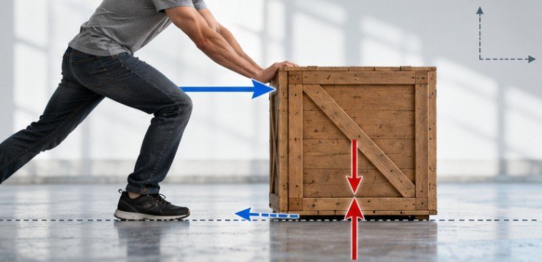
Suppose a 10 kg crate is pushed horizontally to the right with a force of 40 N. Friction acts to the left with a force of 15 N. Assume the crate has no vertical acceleration.
The FBD contains four external forces: weight downward, normal force upward, applied force rightward, and friction leftward.
Using g = 9.8 m/s²:
W = mg = 10 × 9.8 = 98 N
Because there are no additional vertical forces and no vertical acceleration, the normal force is also 98 N.
For the horizontal direction:
Fnet = 40 − 15 = 25 N
Newton’s second law then gives:
a = Fnet ÷ m = 25 ÷ 10 = 2.5 m/s²
The free-body diagram has already done most of the conceptual work. Once the correct forces are identified, the calculations become much easier to organize.
Mistakes That Make Good Math Produce Wrong Answers
One common error is drawing both members of a Newton’s third-law pair on the same FBD.
Suppose a box rests on a floor. The floor pushes upward on the box, while the box pushes downward on the floor. Those forces are equal and opposite, but they act on different objects. Only the force exerted on the box belongs on the box’s diagram. OpenStax makes this distinction clear when discussing Newton’s third law and system boundaries.
Another mistake is drawing a “force of motion.” Velocity and acceleration describe an object’s motion; they are not additional forces. The Illinois mechanics reference specifically excludes kinematic quantities such as velocity and acceleration from a standard FBD.
Students can also accidentally count a force twice by showing both the original angled force and its x- and y-components as separate forces. For calculations, resolve the original force into components, but do not treat those components as new physical interactions.
A Fast Quality Check Before You Solve
A useful final test is to name the source of every arrow: Earth, a surface, rope, spring, fluid, person, motor, or another object. If you cannot identify what produces a force, question whether that arrow belongs.
Then inspect the system boundary, arrow directions, labels, coordinate axes, and any force components. MIT OpenCourseWare specifically uses incorrect-diagram exercises to help students connect FBD symbols with the actual physical interactions they represent.
FAQ
1. Do free-body diagrams include acceleration?
Usually no. Acceleration is not a force. Draw the forces first, then use their vector sum and Newton’s second law to determine acceleration.
2. Should every free-body diagram include friction?
No. Include friction only when the physical situation involves friction or a tendency for contacting surfaces to slide relative to each other.
3. Does the normal force always equal weight?
No. They are equal only under particular conditions, such as a level surface with no additional vertical forces and no vertical acceleration.
4. Where should force arrows start?
For particle models, arrows usually begin at the dot or center. In rigid-body analysis, the point of application matters when forces can produce torque.
The Diagram Is the First Equation
Learning how to draw a free body diagram is really learning how to decide what matters in a mechanics problem. Isolate one system, remove the scenery, keep the external interactions, and make every force direction explicit. Build a daily exam preparation for easy learning.
That is why a strong FBD often makes the algebra feel almost routine. Before reaching for formulas, spend a few seconds testing each arrow against a real interaction and checking the system boundary. A clean diagram will not solve every mechanics problem by itself, but it gives Newton’s laws the correct problem to solve—and that is often the difference between organized reasoning and guesswork.
Leave a Reply