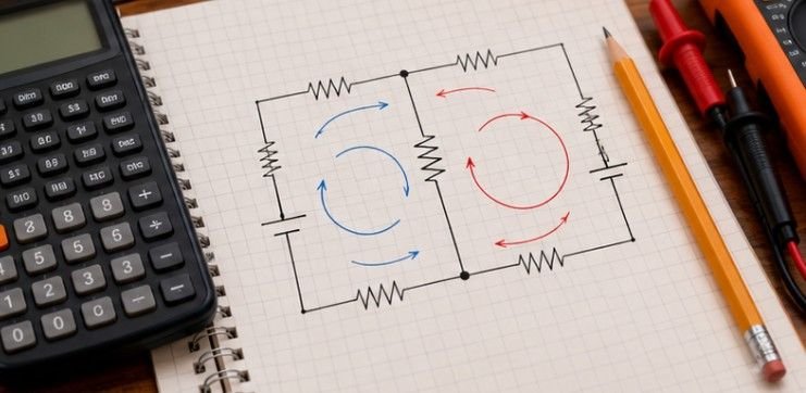
A negative current is not a failed answer. In many kirchhoff’s laws circuit problems, it simply means your guessed arrow points the wrong way. That idea removes much of the fear from multi-loop analysis: choose directions, write consistent equations, and let the algebra reveal the real flow.
Kirchhoff’s rules are conservation laws in circuit form. Kirchhoff’s Current Law follows conservation of charge, while Kirchhoff’s Voltage Law tracks energy changes around a closed circuit path. OpenStax explains that these rules become especially useful when a network can no longer be simplified through ordinary series-and-parallel combinations. MIT OpenCourseWare likewise teaches KCL and KVL alongside node-voltage and loop-current analysis as fundamental methods for studying circuits.
Why Kirchhoff’s Laws Work When Shortcuts Stop Working
Simple resistor networks can often be collapsed into one equivalent resistance. The trouble starts with several voltage sources, junctions, or branches that cannot be classified cleanly as series or parallel.
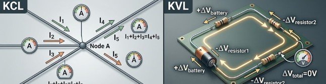
Kirchhoff’s Current Law, or KCL, states:
ΣI = 0
It can also be written as:
ΣIin = ΣIout
The reason is conservation of electric charge. Georgia State University’s HyperPhysics explains that the current entering a circuit junction must equal the current leaving it because charge is not lost at the node.
Kirchhoff’s Voltage Law, or KVL, states:
ΣΔV = 0
For an introductory DC circuit, voltage rises supplied by batteries or other sources balance the voltage drops around a closed path.
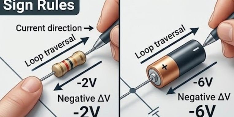
The Sign Rules That Prevent Most Wrong Answers
Most mistakes happen because signs change halfway through a calculation, not because Kirchhoff’s laws are mathematically difficult.
| What you cross | Direction of travel | Loop term |
| Resistor | Same direction as assumed current | -IR |
| Resistor | Opposite assumed current | +IR |
| Ideal voltage source | Negative to positive terminal | +E |
| Ideal voltage source | Positive to negative terminal | -E |
You do not need to know the real current direction before solving the problem. Pick a direction, draw an arrow and stay consistent. If the final current is negative, simply reverse its physical direction when interpreting the answer.
The same habit of carefully labeling directions is valuable elsewhere in physics. For example, compare it with how to draw a free-body diagram before solving force problems.
A Seven-Step Method for Kirchhoff’s Laws Circuit Problems

1. Mark the Essential Nodes
Identify junctions where different circuit branches meet. Points joined only by an ideal wire are electrically the same node and normally do not need separate voltage variables.
2. Assign Branch Currents
Draw an arrow for every unknown branch current. Remember that the arrow represents an assumption rather than a prediction.
3. Write Independent KCL Equations
At each useful node, choose a consistent sign convention. For example, currents entering the node can be positive and currents leaving can be negative.
Avoid writing unnecessary equations that repeat information already provided by another junction.
4. Choose Independent Loops
Select enough closed paths to obtain the missing equations. OpenStax notes that using more loops than necessary may simply generate redundant information.
5. Apply KVL Consistently
Move clockwise or counterclockwise around each selected loop. Record every voltage rise and drop in sequence. Crossing a resistor with the assumed current produces -IR; crossing against it produces +IR.
6. Solve the Simultaneous Equations
For two or three unknown currents, substitution or elimination usually works well. Larger circuits are often easier to manage with matrices.
7. Check the Physics
Insert your solved currents back into at least one KCL equation and one KVL equation. Both should balance, apart from small rounding differences.
Worked Example: Three Branches Between Two Nodes
Suppose nodes A and B are connected by three parallel branches.
Branch 1 contains a 12 V ideal source, with its positive terminal toward A, and a 4 Ω resistor. Branch 2 contains a 6 Ω resistor. Branch 3 contains a 6 V ideal source, also positive toward A, and a 2 Ω resistor.
Assume currents I1, I2 and I3 all point from A toward B.
Define:
V = VA – VB
Applying KVL to the three branches gives:
V = 12 + 4I1
V = 6I2
V = 6 + 2I3
Rearranging:
I1 = (V – 12)/4
I2 = V/6
I3 = (V – 6)/2
Now apply KCL at node A:
I1 + I2 + I3 = 0
Substitute the three expressions:
(V – 12)/4 + V/6 + (V – 6)/2 = 0
Multiply everything by 12:
3(V – 12) + 2V + 6(V – 6) = 0
Simplify:
11V – 72 = 0
Therefore:
V = 72/11 ≈ 6.55 V
Calculate each current:
I1 = (6.55 – 12)/4 ≈ -1.36 A
I2 = 6.55/6 ≈ 1.09 A
I3 = (6.55 – 6)/2 ≈ 0.27 A
The negative value for I1 is useful information. It means the actual current is approximately 1.36 A from B toward A rather than from A toward B.
Check KCL:
-1.36 + 1.09 + 0.27 ≈ 0
The currents balance.
How to Check Your Work Quickly
First, check current balance at important junctions. If entering and leaving currents do not balance, look for an incorrect sign or mislabeled branch.
Next, travel around one complete loop using the final current values. The algebraic voltage change should equal zero.
You can also verify individual resistor values with Ohm’s law:
V = IR
For resistors, power should satisfy:
P = I²R
A practical way to test a circuit before or after solving it is the University of Colorado Boulder’s PhET DC Circuit Construction Kit. It allows students to build virtual circuits and measure current and voltage using simulated meters.
Andrews University also provides a useful equation checker for systems created with Kirchhoff’s laws. It is better used to verify your algebra after you write the equations yourself rather than as a substitute for circuit analysis.
Common Misconceptions and Important Limits
Not every closed loop gives new information. Only independent equations help solve additional unknowns.
A negative current does not automatically indicate an error. It normally tells you that the actual flow is opposite your assumed arrow.
Another common mistake is switching between electron movement and conventional current. Introductory circuit calculations normally use conventional current consistently.
The familiar DC rules also assume a lumped-circuit model. At sufficiently high frequencies, transmission and distributed effects can become important. Similarly, a loop linked by changing magnetic flux requires electromagnetic induction to be considered rather than applying the simplest DC interpretation of KVL without modification.
Frequently Asked Questions
1. What is the easiest way to start a Kirchhoff circuit problem?
Label the nodes, assign current arrows, write KCL equations and then select independent loops for KVL. Consistency matters more than correctly guessing current directions.
2. How many Kirchhoff equations do I need?
You need as many independent equations as unknown quantities. Additional equations that repeat existing node or loop information are redundant.
3. What does a negative current mean?
A negative result means the actual current travels opposite your assumed arrow. The calculated magnitude remains valid.
4. Should I use KCL or KVL first?
Either method can begin the solution, but KCL often helps reduce the number of independent current variables before loop equations are written.
A Better Way to Think About Circuit Analysis
The hardest part of kirchhoff’s laws circuit problems is usually bookkeeping rather than algebra. Label the circuit, commit to assumed directions, apply KCL at junctions, use KVL around independent loops and then test the answer against conservation laws.
Once the signs stop feeling arbitrary, even a complicated circuit becomes a manageable system of equations with physical meaning behind every term. Use simulators after writing the equations yourself. The real skill is not merely obtaining a current value; it is understanding why the circuit must produce that value.
Leave a Reply